Featured

Introducing the car…

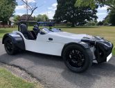
Tiger Super Six with a 2.0L Zetec

I bought my Tiger at the end of August 2019. The car didn’t come with a wealth of history because it had a build blog on PistonHeads.com. I haven’t yet been able to find this blog (I hope I do!) but I will share what I discover about the car as I go.

Here’s the basics. The car was first registered in 2003 and initially had a pinto engine. The pinto let go at a track (the best ending for an engine) and a 2.0L Ford Zetec engine was added as a replacement. The Zetec has had twin Weber carburettors and a modified sump has been fitted. This was done three or four years ago. Since then the car has only done 1,300 miles. I suspect that there is an upgraded head and something has been done with the cams as well but I’m not sure. Best estimation of horsepower is 150 – 155 bhp.

The car look like it has been setup as a track toy. It has an aeroscreen rather than a windshield and no attempt to add comfort items such as a heater (not needed with engine so close to your feet!).

There’s a five speed gear box with a really nice short-shift action, racing/sports clutch and fancy racing cluster (RX-2N).

Block: 2.0L Zetec – Engine Code EDDC (Standard 135PS @6000, 180Nm @4000), Phase 3, Manufactured 1998-2004 for Focus 2.0L, Raceline baffled sump.

Intake: Twin Weber 45DCOE Carburettor

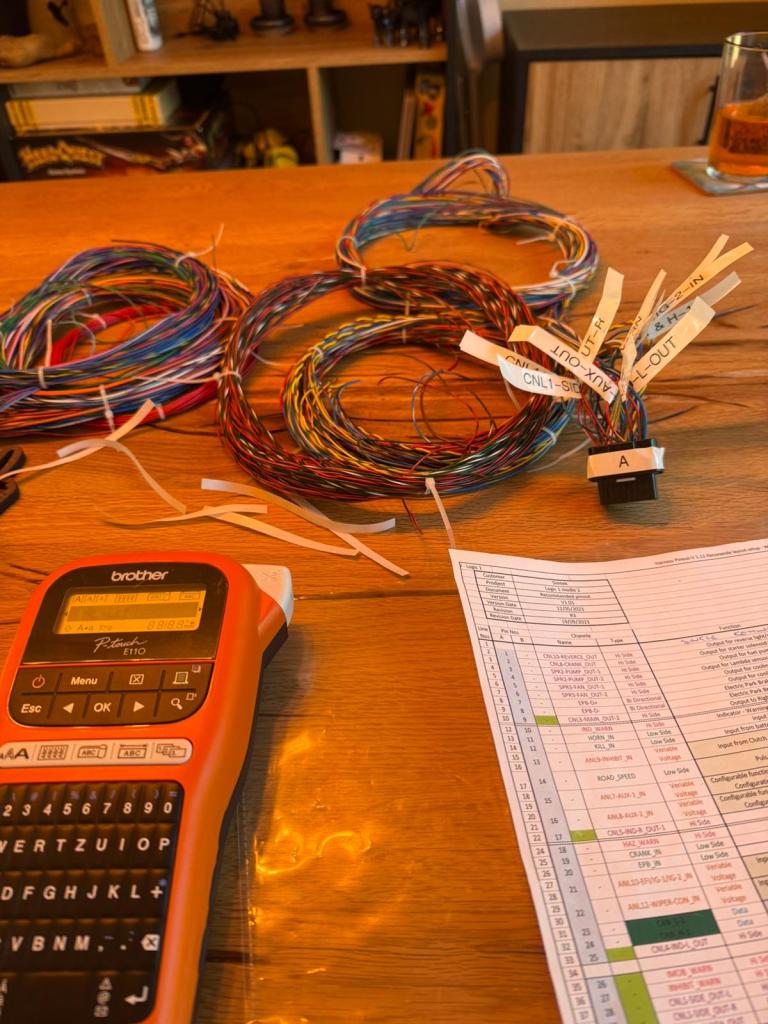
Fuel pump: Inline Facet electronic fuel pump

Cooling: Was a copper radiator with a leak (!), now custom made aluminium radiator by Custom made Rads

Brakes (Front): Was: VW Golf Mk2 – ATE 48mm (?) diameter single piston discs, now replaced with Tiger branded Hi-Spec four piston, fixed brake callipers with EPC green stuff brake pads.

Suspension (Front): Double wishbone with Protech 400 series shock absorbers and 8”, 2.25” ID – 275lb springs

Suspension (Rear): Protech with 8”, 2.25” ID – 180lb springs

Never straight forward

So I’m confused… many who know me would say this is easily done!

Yesterday, I cut all the cable ties and laid out the loom. The plan was to collect the wires into their circuits, separating out those that won’t be needed.

The BCU came with a pin out diagram, basically a spreadsheet listing the function, colour and pin position of each wire. I used this to label up the loom and it seemed correct. The colours of the wires matched their pin positions on the diagram.

The BCU also came with 30 pages of wiring diagrams. Here is where the trouble starts. The wiring diagram also gives the colour of the wire and it’s pin position too. However, these don’t match the pin out diagram! There are some clear mistakes. For example, where a wire is identified on the wrong connector but the correct pin position. This is not that hard to identify. But there are some much more difficult to work through.

The wiring diagram doesn’t give the name/function of the wire so this makes it really challenging to identify which wire in the loom the diagram is referring to. After a couple of hours I’d sorted out the circuits for the daylight running lights (something I don’t currently have but would like to add), reverse lights, hazards and indicators, and an auxiliary circuit.

For these circuits I was able to work through the differences in between the pin out and wiring diagrams with a degree of confidence. Then I hit the ignition circuit. The pin out and wiring diagrams are not even close. There’s a chance that I’m misreading something as the wiring diagram is complex. By necessity it needs to show multiple different ignition options. However, I’ve only been able to find one wire where the pin out and wiring diagrams agree!

I’ve given myself a little space to let things percolate… hopefully when I get back to it this evening or tomorrow, the way forward will seem more obvious!

Wiring Labelling Done

A couple more hours and I now have the loom fully labelled:

I’ve used the codes from the pin out diagram and the labelled and will keep the diagram with the car as a reference. I thought this would be the most logical approach and it helped me to start to get my head around the wiring diagram. The BCU has two connectors (A and B) and if there’s a logic, which I suspect there is, as to which wire is in which pin on what connector, I can’t spot it :D. The wires have come bundled and zip tied together in groups out of the two connectors. I haven’t investigated if this just for convenience or if there has been an attempt to put them in order.

Today, I’m going to work through the wiring diagrams separating the wires out into there different circuits (lights, ignition, aux etc) and then bundle them up that way. Doing this, I’ll also be able to identify the circuits I don’t need. The BCU has a lot of functionality I don’t need (wipers, washers, heater etc). Identifying the circuits in this way might make the task feel a little less overwhelming!

I also need to get back under the car. I’m not an expert in electrics or reading wiring diagrams. There are a few places where understanding how practically the loom will work from the diagram will be easier to understand by looking at the current wiring on the car.

For example (sorry not the best quality image!):

On this lights circuit a 0.35mm RED/black wire comes from the pin and at the black dot splits to the left front and left rear side lights. I can think of any number of ways of implementing this split and googling provides even more! With the little experience I have in this type of job, it’s difficult to assess which is the most robust solution. Tracing some wiring on the car will allow me to establish how the previous builder achieved the same.

I’ve snuck an extra day’s leave from work… it’s just like me to start to build some momentum at the end of a break!

Getting back to it…

Let’s hope that it isn’t a ten month wait for the next post! New job and a thrice weekly commute into London have rather distracted me.

Anyway, started to label up the new loom which plugs into my SimTech BCU.

It’s been so long since any progress, I’ve misplaced the extra cassettes for my labelling machine. Some more arriving tomorrow. Took me a little time to get my head around how to read the pin out diagram but I’ll crack through this in an hour or so, I hope!

Progress…

Progress… well progress, if progress means pulling it apart some more! It’s looking less and less like a car… eek.

Given that a full rewire is underway the scuttle needed to come off along with the various aluminium panels holding the wiring and electronics. I got fully stuck into this task this morning with a good deal of success. The wiring is like a rat’s nest with very little labelling. I’ll get a dedicated page set up to soon to chronicle this activity but thought I’d pop a few pictures up now 🙂

Back to work…

Well it’s been far too long but I have now reached the light at the end of the proverbial tunnel. It’s been some time since my last post… well over two years and the car has sat untouched for this period.

The hiatus was caused by a relative short notice change in living conditions. I was fortunate enough to have accommodation provided by my employer. This ended with around 11 months notice and all spare income, and some that was not (!), was directed to save for a deposit for a new home. Well, we moved into a superb house in June ’23 and now I’ve managed to build up a small war chest to get the Tiger back on the road.

I’m really looking forward to the work. I have Body Control Unit on order which should arrive in the next few weeks and I’ll be putting an order in for an Aim Strada dash. This coupled with the ITB conversion should give me plenty to get stuck into!

Body Logic

On the advice of a member of a kitcar group I’m part of, I’m looking at a BCU. Should be a relatively straight forward way to make the electronic system bullet proof. I’m scheduling a discussion with their sales teams this week.

Only I could change the job of trouble shooting a faulty hazard switch into a full rewire 😉

I’ll report back soon.

A decision looming…

I think that I’m going to commit to doing something a little drastic(ish). I don’t think I know enough about electrics and wiring to fix two (or now three problems). The original hazard problem remains (i.e. right hand side lights not engaging), I have a vampiric charge which flattens the battery when it’s not disconnect, and then there’s the issues created by removing the switches.

I don’t have a wiring diagram for the car and I don’t think the builder followed the wiring diagram provided by Tiger. So… I’m thinking of building a new loom for the lights, fuel pump, and ECU from scratch. This will allow me to build up an understanding of how this works, develop a clear wiring diagram and hopefully address the issues listed above.

I’m 90% sure I’m going to do this as I can build it at home away from the car… make sure it all works and then fit it in. Going to get going on some research as to the bits and pieces I’m going to need to do this.

Electrics!!

So I popped down to the garage this morning and whilst I was there I replaced the spade connector I accidently pulled off last weekend and ‘finished’ replacing the hazard switch. Here’s the situation update:

  • Right hand side indicators still not flashing when hazard switch engaged.
  • Left hand indicators now not flashing when indicator switch engaged but are when hazard switch on.
  • Fuel pump not turning on when fuel pump switch on.

What a mess… this is my opportunity to learn a little more about how to use a multimeter and to figure exactly how the car is wired so that I can get this all working back how it should do. Good job that I enjoy this process.

I’ve picked up my punches and cutting oil from the garage so at least I can finish fabricating the plate that will hold the switches once I figure out the connections!

Some light fabrication

A little bit of light fabrication this morning to make an aluminium template panel to cover the hole in the dash and hold the buttons. If I like it, I’ll keep it… if not I’ll use the carbon fibre panel I made earlier.

I masked off the aluminium’s sheet, used the in snips to cut out the shape and then a hammer and my vice (as an anvil!) to tidy the edges up.

To add the holes I’ll need some cutting oil. This is down at the garage at the moment. It’s a bit chilly but I might pop down to the garage later. If I do this then I’ll be able to replace the spade connector I pulled off last weekend and test the new hazard switch… we’ll see!

Winter plans (continued)

So I’m going to change how I do the blog a bit… I’m not keeping on top of writing up on the pages so I’m going to post a little more. When I’ve completed a job I’ll pull all of the posts together into a page for posterities sake.

I was down at the garage last night removing the panel I cut out and adding in the new hazard switch. Typical me, I was rushing a little at the end (it was cold and dark!) and pulled off one of the spade connectors. With none spare I couldn’t check to see if the new switch had fixed the problem and indeed if I’d connected everything together again properly!

As you can see it was pretty dark by the time I finished. I need to sort out some proper lighting.

With the panel back at home it’s a job for a rainy day to do the fabrication.

The next big job is lined up and ready to go. I’m moving the from a carb setup to ITBs! This was my Christmas present (and next Christmas, and the one after!). New ECU, high pressure fuel system, and some ITBs supplied by DanST Engineering.

A bit intimidated by this but I’ll keep you updated!